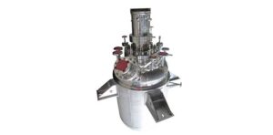
The design of a proper oil or fat hydrogenation agitation system must take into account several requirements, which include:
a. Gas (Hydrogen) Dispersion/Mass Transfer
b. Gas Re-Incorporation
c. Heat Transfer
d. Catalyst Suspension
Gas Dispersion
we utilizes an agitation system which incorporates a combination of impellers to optimize performance. A lower BT-6 gas dispersion impeller located in close proximity to the gas inlet is utilized as the lower impeller.
-
- The BT-6 has a higher pumping capacity than a flat bladed disc impeller D-6 impeller (Rushton) which will improve mass transfer rates increasing reaction rates
- The BT-6 impeller maintains the power during the “gassed” state much better than a D-6 or Rushton impeller. Hydrogenation reactors typically start out with high hydrogen gas rates and then the rate tapers off as the reaction progresses. A conventional D6 impeller forms large cavities behind the blades which results in a substantial drop in hp delivered to the system and loss of mass transfer capability. To combat this issue, a higher speed must be used to increase the power back to normal design limits, which requires a high cost variable speed drive or two-speed motor.The BT-6 impeller develops these cavities at much higher gas flow rates, and hence the power drop is much less (by as much as 60%) as compared to the Rushton, flat-blade turbine. Therefore, the BT-6 design can utilize a single speed motor. Reducing the power drop off in the gassed state by the BT-6 impeller provides the following benefits:
1. More power is available for mixing 2. Expensive two-speed motors or ACVF drives are not required and motor overload potential is reduced since the design does not rely on a speed change for performance
- A combination of the higher pumping capacity and lower power drop off in the gassed state will ensure good suspension of the catalyst used in the hydrogenation reaction.
Gas Re-incorporation
The hydrogenation reaction typically starts with a high hydrogen flow rate to the system. The BT-6 improves mass transfer over the Rushton, flat-bladed design and as such less hydrogen escapes to the surface. It is important to re-incorporate the hydrogen into the batch to maintain the reaction and improve hydrogen utilization. This is very easily and efficiently accomplished by using a 4-bladed pitched impeller (P-4), or impellers, located above the BT-6 impeller. The P-4 impeller:
- Provides increased mixing intensity and draws a vortex for the reincorporation of the hydrogen gas from the vapor space
- With proper design can handle varying liquid levels
- Does not plug of foul as compared to self inducing impellers
- The efficiency of the BT-6 impeller reduces the amount of hydrogen in the gas phase to be reincorporated
Heat Transfer
Hydrogenation reactions also generate a large amount of heat which must be removed from the process. The lower BT-6 does an excellent job of promoting velocity at the heat transfer source (jackets or internal coils). The use of axial flow upper impellers not only reincorporates the gas, but also provides excellent mixing and eliminates zoning in the upper areas of the vessel. Typical upper impellers used include the P-4 impeller and Maxflo W (MW-4) impeller. The MW-4 is a wide-bladed hydrofoil impeller which is well suited for gassing applications which require additional blending for heat transfer. These axial flow impellers provide more flow than self inducing upper impellers and increases the heat removal rate in the hydrogenator.
Catalyst Suspension
In addition to blending and gas dispersion, flow is required in the hydrogenator to suspend the catalyst required for the reaction. The catalyst is typically nickel based and the high flow rate of the BT-6 impeller and upper axial flow impeller(s) provides excellent top to bottom flow to easily and efficiently suspend and distribute the catalyst throughout the vessel.
Salient Features of hydrogenators
- Hydrogenator offered by us utilizes a unique self gas inducing type multiple impeller system.
- The gas in the head space is induced inside the liquid by creating vortex due to top axial flow impellers (high solidity ratio hydrofoil impeller) and narrow baffles in that region.
- The feed gas being sparged through a sparger at bottom and the head space gas brought down by vortexing are, dispersed in fine bubble form by a radial hydrofoil impeller (hollow parabolic
blade) installed at bottom. - Uniform solid particles distribution achieved by providing suitable baffle width in the region of radial flow hydrofoil impeller which creates compartmental axial flow also. Hence our
design is especially useful in real world industrial application involving slurries. - Relative power demand during gassing phase is around 80 to 90% (0.8 to 0.9) of ungassed power, which implies that power of almost similar magnitude as in liquid-solid mixing is being
- utilized for dispersion (breaking) of bubbles. The system hence becomes stable as cavities (voids) are kept at a minimum. Batch time, selectivity, and product quality are improved accordingly.
- Due to the unique multiple impeller system offered by us, system will achieve (i) high pumping (ii) high gas dispersion & (iii) uniform solid suspension etc., simultaneously, using power efficiently & improving heat transfer coefficients also. The distance between the two impellers is optimized to achieve best performance for a particular application.
- Multiple impeller system offered by us will have better control on mass & heat transfer, compared to single impeller system offered by others.
- Our hydrogenators system has been proven in challenging hydrogenations, where other systems were unsuccessful.

